

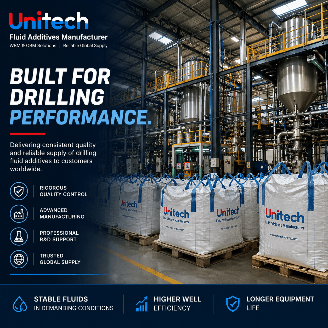
HTHP drilling fluid stability refers to the ability of a drilling fluid system to maintain rheology, filtration control, and emulsion integrity under high temperature and high pressure conditions without structural breakdown.
In engineering terms, HTHP stability is governed by several coupled mechanisms:
· Thermal stability of polymers and colloidal structures in water-based mud (WBM) systems
· Interfacial and emulsion stability in oil-based mud (OBM) systems
· Solid–fluid interaction and suspension stability under thermal stress
Loss of stability typically results from thermal degradation, interfacial film rupture, or electrolyte-induced collapse of fluid structure.
HTHP drilling environments typically involve:
· Elevated downhole temperatures, particularly in deep and high-temperature wells
· High pressure and differential pressure conditions
· High shear during circulation and downhole fluid handling
HTHP Stability = Resistance of fluid microstructure to thermal + mechanical + electrochemical breakdown
This microstructure includes:
· Polymer hydration network (WBM)
· Emulsified droplet interface (OBM)
· Suspended solid framework (both systems)
Most field failures are not “additive shortage problems”, but structural failure mechanisms.
At elevated temperatures:
· Polymer chains undergo scission (chain breakage)
· Molecular weight decreases
· Viscosity and yield point collapse
Thermal degradation can cause persistent loss of rheological performance and may require reformulation or addition of thermally compatible rheology-control additives.
· Rapid PV drop after hot rolling
· Loss of gel strength
· Poor cuttings suspension
At high temperature:
· Emulsifier adsorption layer weakens
· Interfacial tension increases
· Water droplets coalesce
Interfacial film weakening → droplet coalescence → emulsion instability or phase separation
· Sharp ES drop
· Fluid loss spike
· Barite sag onset
High temperature amplifies ionic effects:
· Elevated concentrations of dissolved salts and divalent ions such as Ca²⁺ can alter polymer hydration, clay dispersion, and particle interactions.
· Double layer compression reduces particle repulsion
· Clay aggregation increases
These effects can promote flocculation, changes in rheology, and deterioration of filtration control.
Loss of colloidal dispersion stability
At elevated temperature:
· Fine solids may flocculate or agglomerate
· Changes in particle interactions can alter solids dispersion
· Reduced low-shear carrying capacity can increase the risk of weighting-agent settling and barite sag
HTHP drilling fluid stability depends on three coupled subsystems:
Controls flow behavior under heat
Key components include:
· High-temperature polymers and rheology modifiers (WBM)
· Organophilic clays and rheology modifiers (OBM)
· Low-shear rheology and gel-strength control
· Proper solids concentration and particle-size distribution
Failure mode:
→ network collapse
Controls emulsion integrity
Key components:
· Primary emulsifier → formation and stabilization of the oil-water interface
· Secondary emulsifier → reinforcement and optimization of interfacial stability
Failure mode:
→ droplet coalescence
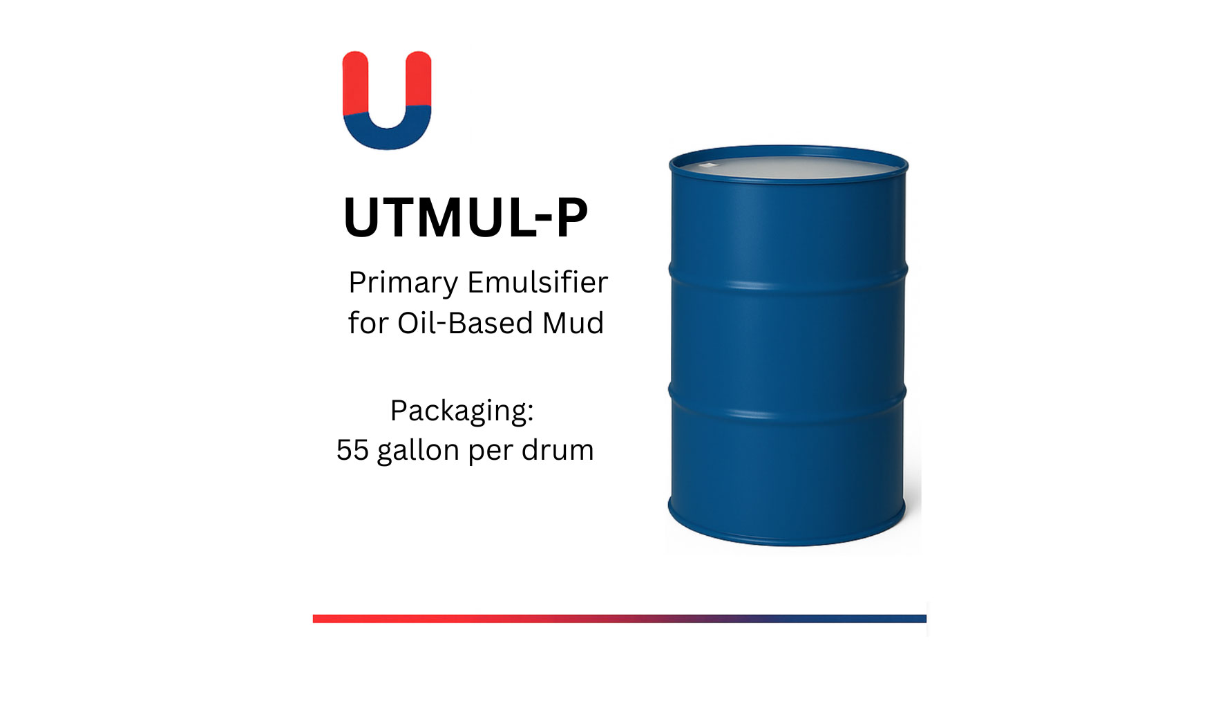
Primary Emulsifier for Oil-Based Mud
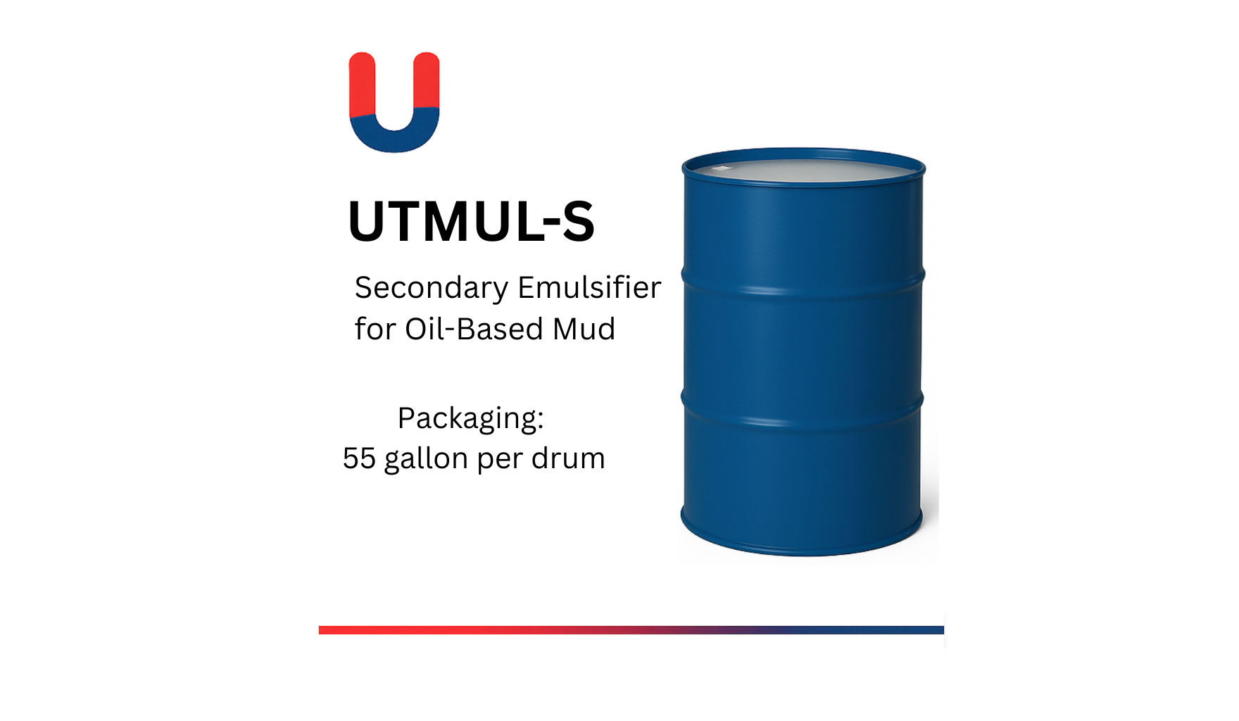
Secondary Emulsifier for Oil-Based Mud
Controls density uniformity
Key components:
· Barite
· Weighting agents
· Gel structure
Failure mode:
→ sag + settling
Measures viscosity retention after thermal aging.
· High RRI → stable polymer network
· Low RRI → thermal degradation
For OBM systems:
· Measures interfacial film strength under heat
· Direct indicator of emulsifier stability
Unlike surface ES measured at 120°F (49°C), HT-ES must be measured under simulated downhole temperature conditions using specialized HTHP cells.
Target: Absolute minimum of 400V (preferably >600V for high-density systems) to ensure the oil-external film remains unbroken.
Indicates filtration barrier integrity under pressure.
Failure = polymer network + solids bridging collapse
Evaluates barite suspension under static + dynamic conditions.
HTHP stability is achieved through system-level design, not single additives.
· OBM → often selected for demanding high-temperature applications because of its strong thermal and emulsion stability
· Advanced WBM → can also be engineered for high-temperature applications when appropriate polymers, fluid-loss-control additives, and dispersion systems are used
· High-temperature polymers (non-linear degradation resistance)
· Dual polymer blending systems
· Thermally stable emulsifier packages
· Organophilic clay reinforcement
· Optimize emulsifier ratio (OBM)
· Balance polymer concentration (WBM)
· Maintain solids dispersion equilibrium
Mandatory testing:
· Hot rolling aging test
· HTHP fluid loss test
· Post-aging rheology measurement
· ES retention test (OBM)
If failure occurs:
· Viscosity loss → polymer network issue
· ES drop → emulsifier interface breakdown
· Sag → suspension system failure
Polymer chain scission under thermal stress
· Increase high-temp polymer fraction
· Reduce low-stability viscosifiers
Interfacial film rupture + coalescence
· Strengthen secondary emulsifier system
· Rebalance emulsifier ratio
Filtration barrier collapse
· Increase thermally stable fluid loss agents
· Improve solids packing efficiency
Loss of low-shear gel network
· Reinforce rheology system
· Improve wetting + suspension synergy
Factor | OBM | WBM |
Stability mechanism | Interfacial film | Polymer network |
Primary failure mode | Emulsion collapse | Polymer degradation |
Thermal resistance | Higher | Moderate |
Sensitivity to salts | Medium | High |
Sag control | Strong | Moderate |
OBM fails at the interface
WBM fails at the molecular structure
For extreme HTHP (>200°C / deep reservoirs):
· Use multi-layer emulsifier systems (OBM)
· Deploy hybrid polymer networks (WBM)
· Maintain ionic equilibrium control
· Minimize fine solid loading
· Optimize shear history management
Problem | Additive/System Focus |
Rheology loss | High-temperature rheology modifiers |
Excessive fluid loss | High-temperature fluid-loss-control additives |
Emulsion instability | Primary/secondary emulsifier system |
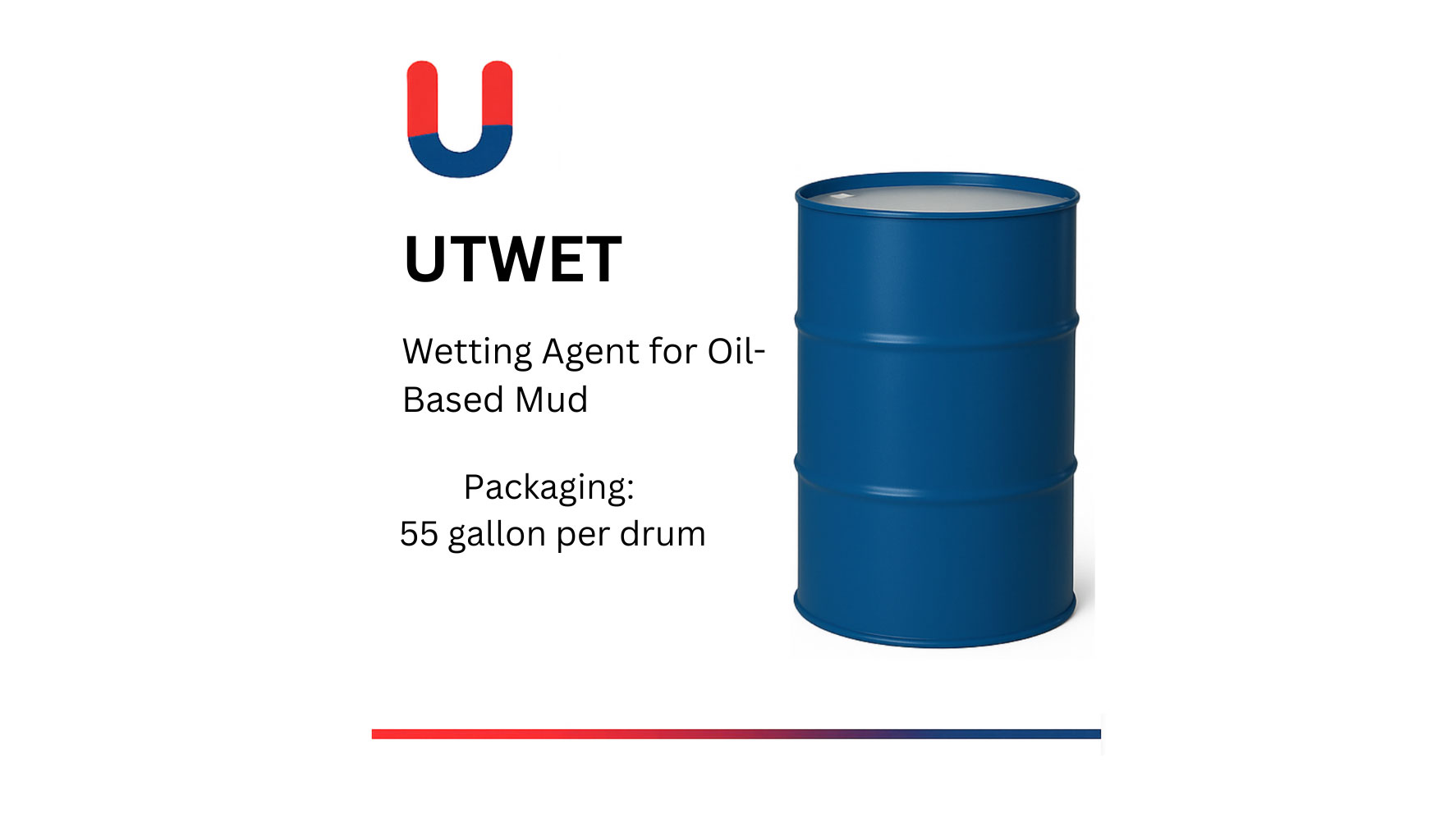
Poor wetting | |
Barite sag | Low-shear rheology and suspension system |
Salt contamination | Salt-tolerant polymers and compatible additives |
Evaluate additives based on:
· HTHP lab aging data
· ES retention curves
· Fluid loss stability profiles
· Deep well case history
· Formulation optimization support
· Real-time troubleshooting capability
· No thermal aging data
· No system-level design support
· Generic “one-grade-fits-all” claims
A stable HTHP system leads to:
· Reduced NPT (non-productive time)
· Lower chemical consumption
· Extended fluid life cycle
· Improved rate of penetration (ROP)
· Reduced wellbore instability risk
HTHP drilling fluid stability is fundamentally a multi-mechanism engineering problem, not a single additive performance issue.
System stability depends on:
· Thermal resistance of polymers
· Integrity of emulsifier interfaces
· Suspension capability of solids
· Ionic equilibrium under stress
Understanding failure mechanisms is the key to designing fluids that remain stable under extreme downhole conditions.
· Oil-Based Mud Emulsifier System Design Guide
· Water-Based Mud Additives Engineering Framework
· Emulsifier Balance & Optimization Guide
· Drilling Fluid Troubleshooting Field Manual
If you are experiencing:
· HTHP emulsion breakdown
· Severe viscosity loss
· Fluid loss instability
· Barite sag in deep wells
We can provide:
· Custom HTHP fluid system design
· Laboratory simulation & testing
· Field-validated additive optimization